Whats is an RfmUsb Adapter
An RfmUsb is a USB 2.0 device that exposes the functions of the Hope RFM69 radio modules over a serial command line interface (CLI). It can be used with any modern OS as it enumerates as a standard CDC usb device.
Hardware Overview
The RfmUsb device supports the RFM69HCW radio module. An ATSAMD21E18A mcu performs USB and CLI processing functions.
* A future version may support the RFM95 module which is an FSK/OOK and Lora capable radio
RM69HCW Module Specifications
- +20 dBm - 100 mW Power Output Capability
- High Sensitivity: down to -120 dBm at 1.2 kbps
- High Selectivity: 16-tap FIR Channel Filter
- Bullet-proof front end: IIP3 = -18 dBm, IIP2 = +35 dBm,80 dB Blocking Immunity, no Image Frequency response
- Low current: Rx = 16 mA, 100nA register retention
- Programmable Pout: -18 to +20 dBm in 1dB steps
- Constant RF performance over voltage range of module
- FSK Bit rates up to 300 kb/s
- Fully integrated synthesizer with a resolution of 61 Hz
- FSK, GFSK, MSK, GMSK and OOK modulations
- Built-in Bit Synchronizer performing Clock Recovery
- Incoming Sync Word Recognition
- 115 dB+ Dynamic Range RSSI
- Automatic RF Sense with ultra-fast AFC
- Packet engine with CRC-16, AES-128, 66-byte FIFO Built-in temperature sensor
Full RFM69 Specification RFM69HCW
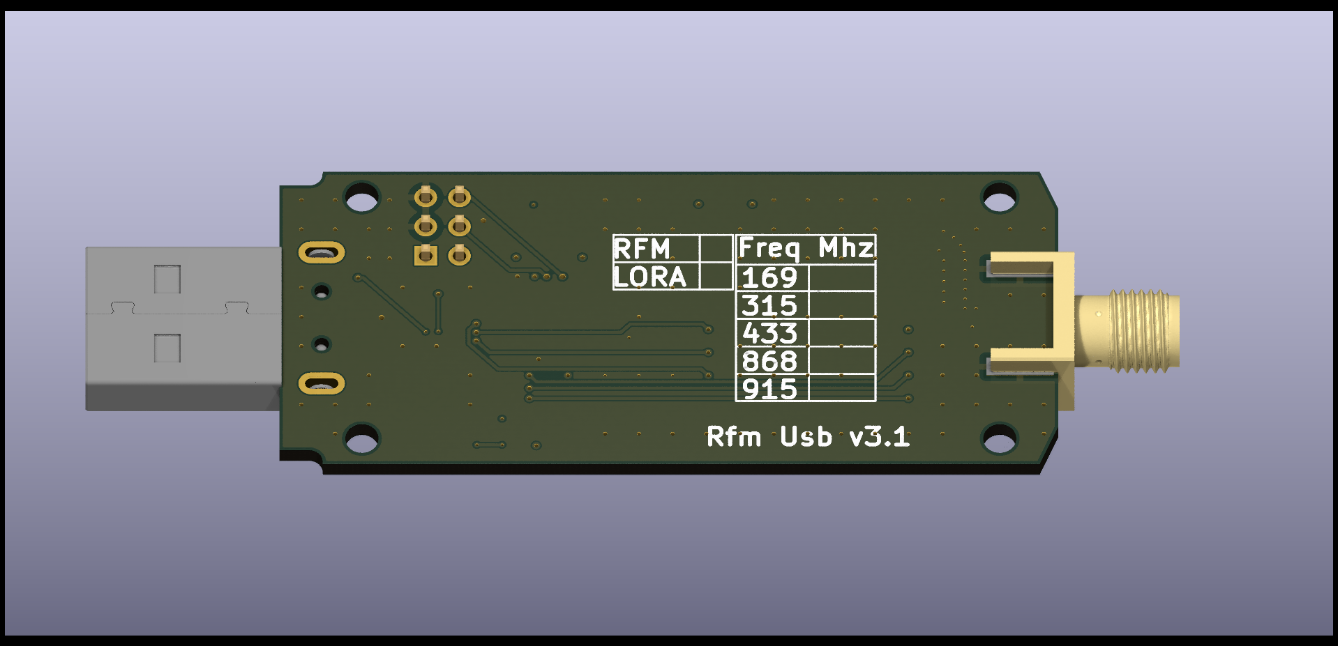
Supported Frequencies
- 315 Mhz
- 433 Mhz
- 868 Mhz
- 915 Mhz
* Dependant on module variant installed on the RfmUsb board
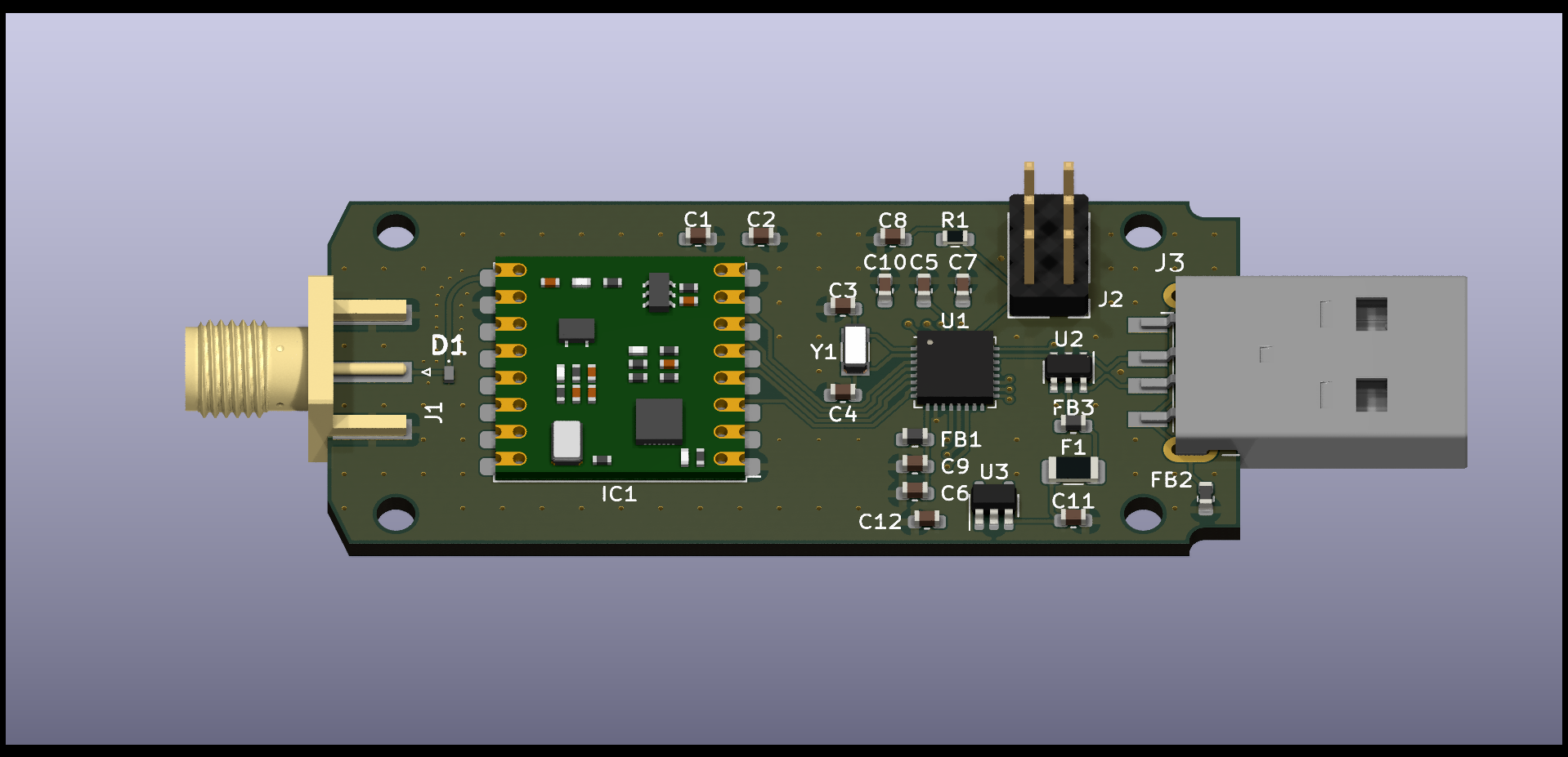
Front View

Back View

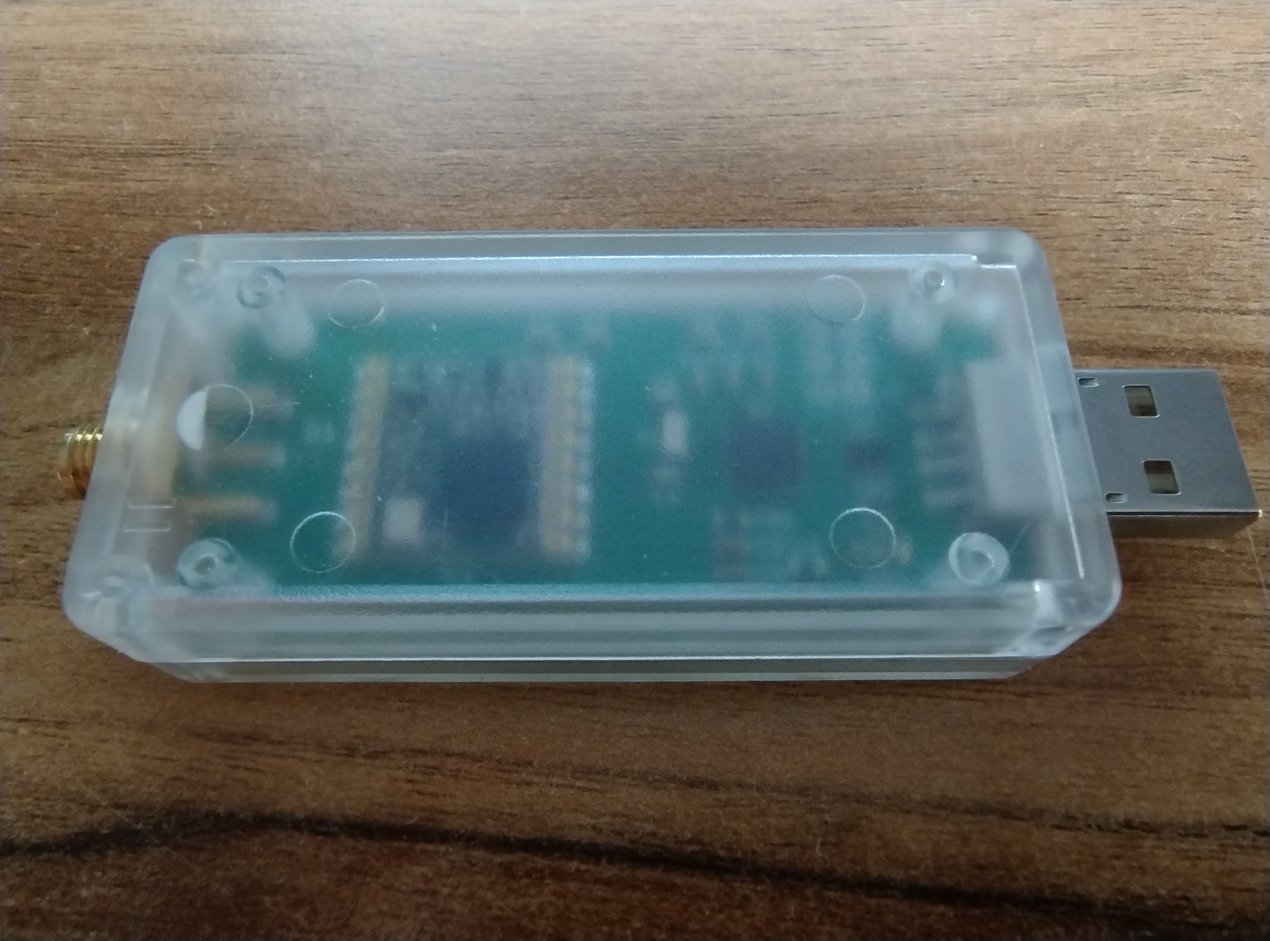
Protective Case

Connectors
| Connector | Description |
|---|---|
| J1 | 50 Ohm SMA female connector |
| J2 | 6 way 2.54mm pitch ISP header (not populated) |
| J3 | USB 2.0 Type A |
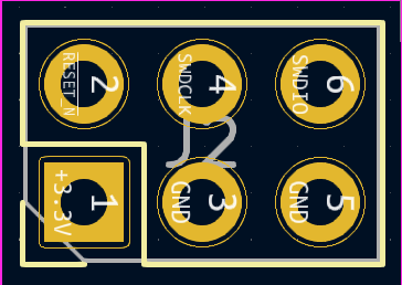
ISP Header
The in system programming header (ISP) can be used to flash the device with a boot loader or full flash image. It can also be used with an appropriate debugger to debug application code on the device.
| Pin | Name | Function |
|---|---|---|
| 1 | VCC | Power supply ground 3.3v |
| 2 | RESET | Active low reset |
| 3 | GND | Power supply ground |
| 4 | SWDCLK | Serial Wire Debug Clock. |
| 5 | GND | Power supply ground |
| 6 | SWDIO | Serial Wire Debug Data Input/Output |

Firmware Update
The firmware on the device can be updated via the UF2 boot loader that is installed on the RfmUsb device. The boot loader can be entered by two mechanisms, via a cli command or via a double reset. A double reset of the device will enter the UF2 boot loader. A double reset can be performed by plugging the device into a usb port and connecting the RESET (Pin 2) on the ISP port to GND (PIN 3 or 5).
Serial Device Configuration
When the device is plugged into a modern operating system it will be enumerated as a CDC Usb serial device and assigned a com port number from the operating system. The following configuration can be used when connecting to the serial device:
| Setting | Setting |
|---|---|
| Baud Rate | 1200 - 230400 |
| Data Bits | 8 |
| Parity | None |
| Stop Bits | 1 |
Serial Terminal Applications
Windows: coolterm
Linux: minicom
Command Line Instructions
When the device is connected to with a serial console application the CLI command help retrieves the full list of available CLI commands. CLI Commands are terminated by either a CR or LF character. A CR or LF character entered will repeat the last CLI command.
The full list of commands is available rfmusb commands
CLI Execution
When a CLI command executes successfully the device responds with an OK. When a CLI command parameter or execution fails the device will return an error response.
CLI Parameters
A number CLI commands have required parameters, these are denoted in the command help description.
For example s-br Set bit rate: 1200-300000
The CLI commands will accept parameters in either decimal or hexadecimal format.
Optional CLI command parameters are denoted with square braces surrounding the parameter.
For example e-tx Execute tx: hex [tx count: 1 - 20] [tx interval: 10 - 1000] [timeout: 10 - 5000]. tx count, tx interval and timeout are all optional arguments.
A number of CLI commands require hexadecimal parameters. These are denoted with the following syntax hex (min - max). The minimum and maximum values specify the hex minimum and maximum string length.
An example CLI command that accepts a hex string value as a parameter s-sync AA55BE
Most CLI commands are simple getter setter type commands for example g-om Get operating mode and s-om Set operating mode: 0-5
CLI DIO Commands
The Rfm69 device has a number of digital IO pins (DIO) these pins are used to signal to the MCU the internal state of the packet engine. The MCU will signal state changes to the connected serial console when the state of one of the DIO pins changes.
First the DIO mapping needs to be set see Section 5.3.2 of the RFM69HCW specification of the configurations.
Set the DIO0 line mapping to Mapping 0 s-dio 0 0
The response to this CLI command is as follows OK-[0x0003]-Map 03
This will enable the DIO0 line to signal CrcOk Irq state change in RX mode. In Tx mode the DIO0 line will signal PacketSent Irq state change.
The DIO interrupt mask must be set to enable the interrupt to be signalled to the client serial console application. The DIO0 Irq can be enabled with the DIO mask CLI command s-dim 1
When the DIO Irq occurs the serial console application will be notified with a DIO IRQ PIN interrupt DIO PIN IRQ [0x01]. The Irq flags can be read tp determine the radios Irq state.
CLI Irq Flags Command
The device Irq flags can be read with the get Irq flags CLI command g-irq. This will return the list of Irq flags and their current status.
0:CRC_OK
0:PAYLOAD_READY
0:PACKET_SENT
0:FIFO_OVERRUN
0:FIFO_LEVEL
0:FIFO_NOT_EMPTY
0:FIFO_FULL
0:ADDRESS_MATCH
0:AUTO_MODE
0:TIMEOUT
0:RSSI
0:PLL_LOCK
0:TX_RDY
0:RX_RDY
1:MODE_RDY
| Flag | Description |
|---|---|
| CRC_OK | Set in Rx when the CRC of the payload is Ok. Cleared when FIFO is empty. |
| PAYLOAD_READY | Set in Rx when the payload is ready (i.e. last byte received and CRC, if enabled and CrcAutoClearOff is cleared, is Ok). Cleared when FIFO is empty. |
| PACKET_SENT | Set in Tx when the complete packet has been sent. |
| FIFO_OVERRUN | Set when FIFO overrun occurs. |
| FIFO_LEVEL | Set when the number of bytes in the FIFO strictly exceeds FifoThreshold, else cleared. |
| FIFO_NOT_EMPTY | Set when FIFO contains at least one byte, else cleared |
| FIFO_FULL | Set when FIFO is full (i.e. contains 66 bytes), else cleared. |
| ADDRESS_MATCH | Set when Sync and Address (if enabled) are detected. |
| AUTO_MODE | Set when entering Intermediate mode. |
| TIMEOUT | Set when a timeout occurs |
| RSSI | Set in Rx when the RssiValue exceeds RssiThreshold. |
| PLL_LOCK | Set (in FS, Rx or Tx) when the PLL is locked. |
| TX_RDY | Set in Tx mode, after PA ramp-up. |
| RX_RDY | Set in Rx mode, after RSSI, AGC and AFC. |
| MODE_RDY | Set when the operation mode requested is ready |
CLI Tx Command
To transmit a packet a number of times with a fixed delay between each transmission the execute tx CLI command can be used e-tx Execute tx: hex(1-64) [tx count: 1 - 20] [tx interval: 10 - 1000] [timeout: 10 - 5000]
This function is useful for switching simple one way radio controlled OOK socket and switched adapters.
CLI Buffered Io Command
By default the Rfm69 devices support a maximum fifo size of 66 bytes. There are some scenarios that require a larger packet size to be transmitted or received. The RfmUsb supports transmission of of a larger packet of 256 bytes, via a buffered io. Buffered io can also process packets smaller than the FIFO size. By default the buffered io feature is not enabled and must first be enabled using the set buffered io enabled CLI command s-be 1.
Large packet transmit
To transmit a large packet via buffered io there are a number of steps are steps required:
To transmit a large packet the io buffer is filled using the write io buffer CLI command w-b. Each write allows up to 64 bytes at a time expressed as a hex string. When the buffer has been written with the number of bytes to be transmitted the radio mode must be set to Tx (s-om 3). The execute io buffer transmit CLI command is used to transmit the contents of the buffer (e-btx). The buffer will be transmitted synchronously during the execution of the (e-btx) command.
- Configure the RfmUsb radio
- Setup the PacketFormat to either fixed or variable length
- Enable the IO buffer via the BufferedIoEnable setting
- Write the message bytes to the IO buffer
- Set the radio Mode to TX
- Execute the buffered io transmit
s-pf 1
s-be 1
w-b AA55AA55AA55
s-om 3
e-btx
Large packet receive
To a receive a large packet via buffered io there are a number of setup steps required:
- Configure the RfmUsb radio
- Set the Dio mapping for Dio0 to DioMapping1 to capture the PayloadReady Irq
- Set the Dio mapping for Dio1 to DioMapping2 to capture the FifoNotEmpty Irq
- Setup the PacketFormat to either fixed or variable length
- Set the PayloadLength to 0xFF
- Enable the IO buffer
- Set the radio Mode to RX
- Wait for the PayloadReady Irq
- Read the message bytes from the io buffer
s-dio 0 1
s-dio 1 2
s-pf 1
s-pl 0xFF
s-be 1
s-om 4
r-b